

Hidden defects-the occurrence and impact of cracks
In the process of daily use or assembly and repair, the printed circuit board inside the equipment will inevitably be affected by various mechanical stresses, including bending stress. The bending of the printed circuit board causes the force to be transferred to the surface mounted multilayer ceramic capacitor through solder. These forces are concentrated at the bottom of the capacitor, but the ceramic material is hard, inelastic and fragile.
When the bending force is large enough, the ceramic material on the bottom side of the capacitor will crack (see Figure 1).

Fig. 1 Schematic diagram of ceramic crack caused by typical bending
The crack generally starts from the bottom of the capacitor and extends in the ceramic at an angle of 45 degrees. It usually ends at the end electrode, or it may continue to extend to the top of the ceramic, and then ends. This crack may cause the whole end of the ceramic capacitor to separate from the main body. Once the crack occurs, the electrical parameters of the capacitor may not change significantly. In the next few hours, days, even weeks, it can still maintain the same capacitance, loss tangent or ESR (equivalent series resistance) as before, but the generation of cracks establishes a foundation for future electrical faults. The generation of cracks may cause water vapor and ions to continuously penetrate into the capacitor in the following time. A very "tight" crack may take more time to turn into an electrical fault. If the fault part is exposed to high current, local heating will be generated inside the crack, which will lead to the failure of the capacitor, and the whole circuit will eventually fail.
In order to evaluate the bending capacity of ceramic capacitors, the bonding strength test of end coating is widely used in the reliability research of capacitors.
Test method for bonding strength of end plating
The bonding strength test of end plating is also called substrate bending test. Before the test, the capacitor is installed in the center of a specific printed circuit board. Taking GB / T 2693-2001 as an example, the test sample is required to be installed on an epoxy screen glass printed board with a length of 100 mm and a thickness of 1.6 mm.
The bonding strength test of end plating generally includes the following steps:
1) Place the PCB in the bending test device with the capacitor facing down, and test the capacitance C0 before the test when the PCB is in the horizontal state;
2) The bending tool can make the bending depth (d) reach 1 mm at the speed of 1 mm / s ± 0.5 mm / s to maintain the bending state of the circuit board for 20 s ± 1 s (see Fig. 2);
3) Test the capacitance C after the test under the bending state of printed circuit board, and monitor the electrical parameters of the whole bending state if necessary;
4) Reset the bending test device to restore the circuit board from the bending state and remove it from the test device;
5) Check the appearance of the test sample.
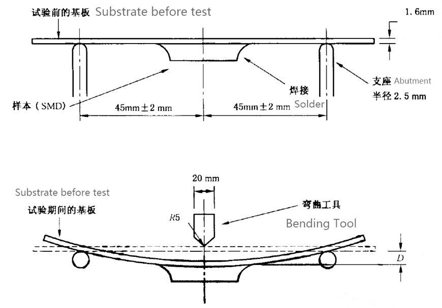
Fig. 2 bending test device
When the step-by-step bending method is used to find the limit of the bending capacity of the test sample, the bending tool can make the bending depth (d) reach 1 mm, 2 mm, 3 mm, 4 mm and 5 mm respectively at the speed of 1 mm / s ± 0.5 mm / s, and the bending state of the circuit board can be maintained for 20 s ± 1 s when the depth is reached, and then the capacitance is tested.
Mechanical model of bonding strength test of end plating
The stress analysis of the test base plate shows that the base plate is mainly affected by the supporting force provided by the supports on both sides and the pressure P exerted by the bending tool. In the actual test, the width of the bending tool and support of the test device is greater than the width of the test base plate by 20 mm, and the base plate will not be affected by torque. Therefore, the model is regarded as a two-dimensional three-point bending model, as shown in Fig 3.
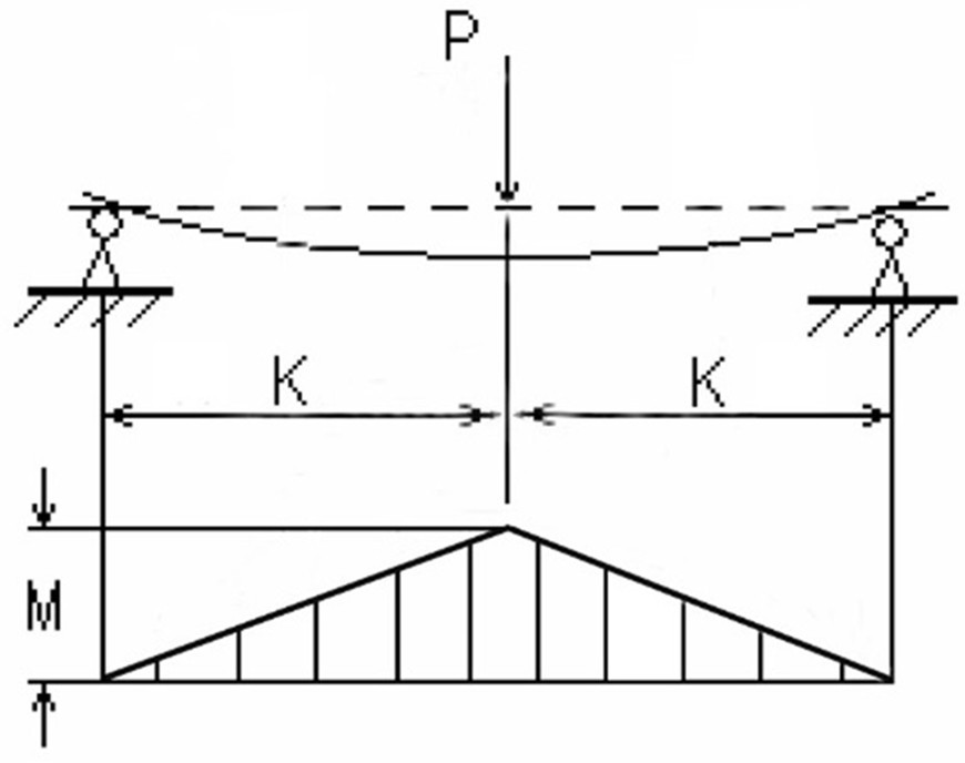
Fig.3. 3 points bending model of test substrate
|
The bending moment in the middle of the test base plate is M = PK, where K is the distance between the pressure P and the support of the test device. |
|
|
The maximum bending normal stress in the middle of the test substrate is |
|
|
The stress position is the lower surface of the test substrate, which shows tensile stress, where W is the bending section coefficient. The cross section of the test substrate is rectangular, therefore: |
|
|
Where B is the width of the test substrate and H is the thickness of the test substrate; In the end: |
|
|
Bending shear stress of test substrate under pure bending state. |
|
Experimental phenomena and result analysis
Through the analysis of the test results of the bonding strength of the end coating, it is found that there are three main situations between the capacity change rate (c-c0) / C0 and the bending depth (d): as shown in Figure 4:
1. With the gradual increase of the bending depth (d), the capacity change rate does not change significantly. After reaching a certain depth, the capacity change rate drops sharply. When the test substrate is restored to the flat state again, the capacity change rate will decrease rapidly, Capacity is restored;
2. As the bending depth (d) increases, the capacitor fails. When the test substrate is restored to the flat state, the capacity does not recover;
3. With the increase of bending depth (d), the capacity change rate does not change significantly.
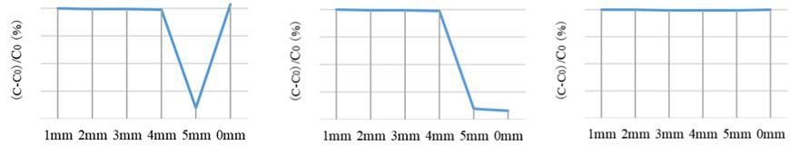
Fig. 4 Relationship between depth of reduction and capacity of end plating bonding strength test
During the test, due to the cracks in the ceramic material of the capacitor, accompanied by the fracture of some electrodes, it may temporarily cause some loss of capacity, so the capacity change rate decreases. However, once the strain is eliminated, the electrodes can be "combined", and when the electrodes are connected again, the lost capacitance will be restored. In many cases, especially when the bending depth (D) is small, the cracks caused by the test cannot be evaluated by visual inspection or electrical performance testing. We regard these cracks as hidden defects. After the end coating bonding strength test, the climate sequence test can further evaluate whether the sealing of the test sample is damaged, and further evaluate the impact of these hidden defects on the reliability of MLCC.


 IPv6 network supported


