Voltage :
25V-500VSize :
0402-1206Dielectric :
2C1Features
Small size with low ESL.
High self-resonant frequency, excellent filtering performance, can effectively suppress circuit noise.
Reduce the number of capacitor used.

Product Applications
Suitable for military communication, radar, shell fuze, shipboard, aviation, aerospace system and other electronic equipment and civil high-end equipment.
Suitable for filtering and decoupling in digital circuits.
Ordering Information
| CT41G | 1206 | 2R1 | 100V | 105 | K | F | B |
| Series | Case size | Dielectric | Rated voltage | Capacitance | Capacitance tolerance | Termination finish | Internal electrode |
|
CC41: Class l CT41G: Class ll |
0402 0603 0805 1206 |
CG(Class l) 2R1(Class ll) 2C1(Class ll) |
25V 50V 100V 250V 500V |
Refer to Capacitance and Rated Voltage Range |
C=±0.25pF D=±0.5 pF J=±5% K=±10% M=±20% |
F | B |
Dimensions
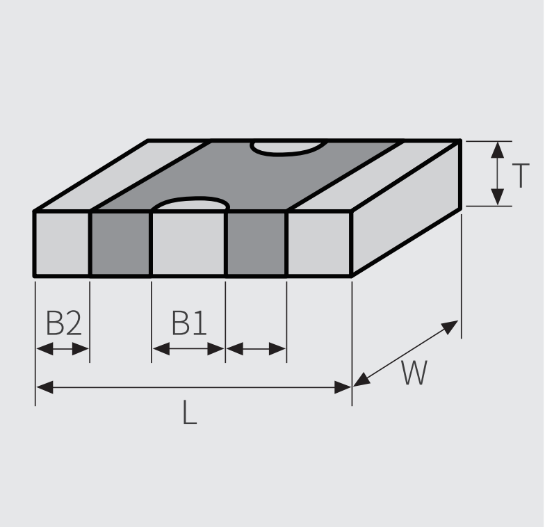
|
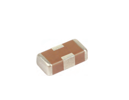
Appearance |
Size Code |
0402 |
0603 |
0805 |
1206 |
 |
L |
1.00±0.20 |
1.60±0.20 |
2.00±0.30 |
3.2±0.3 |
|
W |
0.50±0.20 |
0.80±0.20 |
1.25±0.20 |
1.6±0.3 |
|
|
Tmax |
0.70 |
1.00 |
1.45 |
1.80 |
|
|
B1 |
0.30±0.10 |
0.30±0.20 |
0.60±0.20 |
0.95±0.30 |
|
|
B2 |
0.25±0.10 |
0.35±0.25 |
0.50±0.25 |
0.50±0.35 |
Electrical Characteristics
| Characteristics | Dissipation Factor(CR Unit: pF) | Dielectric Strength | Insulation Resistance 25℃ | Operating Temperature Range |
| 2C1 |
tgδ≤3.5% |
2.5UR |
UR≥1000MΩ |
-55℃ to ~125℃ |
Product Structure
1. Product structure and equivalent circuit

2. Noun explanation
A. Insertion loss
Insertion loss is an important index to measure the suppression ability of three-terminal chip multilayer ceramic capacitors to interference signals. It is before and after the product is connected to the circuit, the laboratory measurement is generally carried out under a specific 50Q impedance system. Insertion loss (1) is a function of frequency, expressed as dB, and the formula is:
IL=20 log(V1/V2)
B. Rated current
Rated current is the maximum operating current without reducing the insertion loss characteristic when the product is operating normally within the operating temperature range. In general, the greater the rated current, the greater the volume and capacity of the product.
C. DC resistance
DC resistance is the resistance presented by the direct current on the element, that is, the inherent static resistance of the element, does not contain reactance value.
3. Selection of products
According to the requirements and characteristics of the circuit to choose the appropriate product size
Need to use three terminal chip multilayer ceramic capacitor instead of ordinary ceramic capacitor, can be based on the principle of "high generation of low", that is, the rated voltage is high instead of rated voltage low, with a small capacity with temperature change rate instead of large, high quality grade instead of low quality grade.
Select the appropriate product according to the frequency or frequency range of noise removal.
4. Welding and erection
The correct installation method should be adopted. For the basic welding and precautions, please refer to "Electric Installation Process" in "Application Guide of Ceramic Capacitors" in this manual. Other instructions are as follows:
A. Bonding pad recommended

B. Pad design
To improve the filtering effect, it is recommended to use the through-hole design at the grounding terminal. Pad area should be designed as large as possible; Make through-holes and connect them to the grounding mode mounting side of the chip. The through-holes should be designed to be as close to the grounding end as possible.

5. Other Matters needing attention
(1) Do not use the product beyond rated current and rated voltage to avoid thermal breakdown, etc.
(2) Do not apply the filter to the temperature exceeding the upper limit of the operating temperature;
(3) Good storage conditions, see the manual "Ceramic capacitor application Guide" in point 4 "supplementary instructions" 2 storage conditions.