Lead-free terminations, RoHS and Reach Compliant
Capacitance :
100pF to 47μFVoltage :
4V - 200VTorlarance :
±5%,±10%,±20%Size :
0201 to 2225Dielectric :
X7RFeatures
Torch brand Chip capacitors are of small size and light weight. They are non-polar and thus are easy to install. The X7R dielectric is classified as class II material, suited for bypass and decoupling applications or for frequency discriminating circuits where Q and stability of capacitance characteristics are not critical. Ceramic capacitors using this type of dielectric are considered to be “stable”, with a predictable change in capacitance limited to ±15% from −55°C to +125°C, with respect to time and voltage, boasting a minimal change in capacitance with reference to ambient temperature.
Ordering Information
|
CT41G |
-0805 |
-X7R |
-50V |
-100pF |
-K |
-N |
-T |
|
Series |
Case size |
Dielectric |
Rated voltage |
Capacitance |
Capacitance tolerance |
Termination Finish |
Packaging |
|
CT41G- Class II Ceramic |
0201 0402 0603 0805 1206 1210 1812 2220 2225 |
X7R |
4V 6.3V 10V 16V 25V 50V 100V 200V |
Refer to Capacitance and Rated Voltage Range |
J=±5% K=±10% M=±20% |
N=100% Sn |
T=7” Reel |
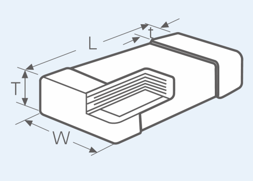
Dimensions

|
|
|
|
|
|
|
|
|
|
Unit:mm |
|
Size Code |
0201 |
0402 |
0603 |
0805 |
1206 |
1210 |
1812 |
2220 |
2225 |
|
L |
0.60±0.03 |
1.00±0.20 |
1.60±0.20 |
2.00±0.30 |
3.2±0.3 |
3.20±0.30 |
4.50±0.40 |
5.70±0.50 |
5.70±0.50 |
|
W |
0.30±0.03 |
0.50±0.20 |
0.80±0.20 |
1.25±0.20 |
1.6±0.3 |
2.50±0.30 |
3.20±0.30 |
5.00±0.50 |
6.50±0.60 |
|
Tmax |
0.35 |
0.70 |
1.00 |
1.45 |
1.90 |
2.80 |
3.50 |
4.20 |
4.20 |
|
t |
0.15±0.05 |
0.25±0.10 |
0.35±0.25 |
0.50±0.25 |
0.50±0.35 |
0.60±0.30 |
0.90±0.60 |
0.90±0.60 |
0.90±0.60 |
Electrical Characteristics
|
Item |
Specification Limits |
Measuring Conditions |
|
|
Operating Temperature Range |
C0G |
-55℃ to +125℃ |
— |
|
X7R |
|||
|
X5R |
-55℃ to +85℃ |
||
|
Capacitance |
Within specified tolerance |
— |
|
|
Q |
C0G |
CR≤30 pF: Q≥400+20CR CR>30 pF: Q≥1000 |
C0G: CR≤1000PF 1MHz±10% 0.5V-5V CR>1000pF 1kHz±10% 1V±0.2V
X7R & X5R: CR≤10uF 1kHz±10% 1V±0.2V CR>10uF 120Hz±10 0.5V±0.2V |
|
X7R X5R |
UR≥50V , tgδ≤3.5%; 25V≤UR<50V , tgδ≤5.0%; 16V≤UR<25V , tgδ≤7.0%; 4V≤UR<16V , tgδ≤10%; ※Note: CR≥1μF,tgδ≤10 %; Size 0201,0402,0604 , tgδ≤10 %; |
||
|
Insulation Resistance |
10000MΩ or 100MΩ·μF whichever is less |
Rated voltage shall be applied within following conditions: UR≤500V UR UR>500V 500V Voltage applying time shall be 60±5 seconds, charging and discharging current shall be 50mA or less. |
|
|
Dielectric Strength |
No breakdown or visual defects |
250% of DC rated voltage for 5 seconds, charging and discharging current shall be 50mA or less. |
|
Storage
To maintain the solderability of terminal electrodes and to keep packaging materials in good condition, measures should be taken to control temperature and humidity.
*Recommended conditions:
Even under ideal storage conditions, solderability of capacitors is deteriorated as time passes, so capacitors shall be used within 12 months from the time of delivery. When exceeding the above period, please check solderability before applying the capacitors to your circuit.
Applications
Typical applications include critical timing, tuning, circuits requiring low loss, circuits with pulse, high current, decoupling, bypass, filtering, transient voltage suppression, blocking, and energy storage.
--------------占位---------------